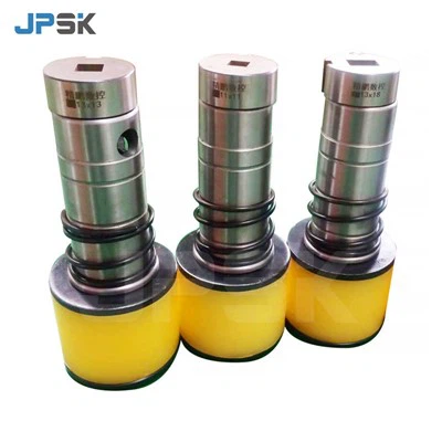
Determining the cutting depth of cutting molds is a crucial aspect in the manufacturing and processing industries. As a cutting molds supplier, I've encountered numerous clients who struggle with this issue. In this blog, I'll share some key factors and methods to help you accurately determine the cutting depth of cutting molds.
Understanding the Basics of Cutting Depth
The cutting depth refers to the distance that the cutting edge of the mold penetrates into the workpiece during the cutting process. It directly affects the quality of the cut, the tool life, and the overall efficiency of the machining operation. An improper cutting depth can lead to issues such as rough cuts, excessive tool wear, and even damage to the workpiece.
Factors Affecting Cutting Depth
Material Properties of the Workpiece
The material of the workpiece is one of the most significant factors influencing the cutting depth. Different materials have different hardness, toughness, and brittleness. For example, soft materials like aluminum and copper can generally tolerate a larger cutting depth compared to hard materials such as stainless steel or titanium.
When cutting soft materials, a deeper cutting depth can be used to increase the material removal rate. However, for hard materials, a shallower cutting depth is often necessary to avoid excessive tool wear and breakage. The following table shows some general guidelines for cutting depths based on different materials:
| Material | Recommended Cutting Depth (mm) |
|---|---|
| Aluminum | 2 - 5 |
| Copper | 1 - 3 |
| Mild Steel | 0.5 - 2 |
| Stainless Steel | 0.2 - 1 |
| Titanium | 0.1 - 0.5 |
Tool Geometry and Material
The geometry and material of the cutting mold also play a vital role in determining the cutting depth. Tools with a sharp cutting edge and proper rake angle can generally cut deeper than those with a dull edge. Additionally, the material of the tool affects its wear resistance and cutting performance. High - speed steel (HSS) tools are suitable for general cutting operations, while carbide tools are more appropriate for high - speed and high - precision cutting, allowing for a relatively larger cutting depth.
For example, a carbide cutting mold with a well - designed geometry can cut deeper into a hard workpiece compared to an HSS mold under the same cutting conditions. The choice of tool geometry, such as the rake angle, clearance angle, and cutting edge radius, should be optimized according to the specific workpiece material and cutting requirements.


Machine Tool Capability
The capabilities of the machine tool used for cutting are another important consideration. The power, rigidity, and feed rate of the machine tool limit the maximum cutting depth that can be achieved. A machine tool with high power and good rigidity can support a larger cutting depth, while a less powerful or less rigid machine may require a shallower cutting depth to avoid vibration and poor cutting quality.
For instance, a heavy - duty CNC machining center can handle deeper cuts compared to a small benchtop milling machine. Before determining the cutting depth, it's essential to consult the machine tool's manual to understand its specifications and limitations.
Methods for Determining Cutting Depth
Trial and Error Method
The trial and error method is a simple yet effective way to determine the appropriate cutting depth. Start with a relatively shallow cutting depth and gradually increase it while observing the cutting quality, tool wear, and machine performance. If the cut is smooth, the tool wear is within an acceptable range, and the machine operates stably, the cutting depth can be further increased. However, if any issues such as excessive vibration, rough cuts, or rapid tool wear occur, the cutting depth should be reduced.
This method requires some experience and patience, but it allows you to fine - tune the cutting depth based on the actual cutting conditions. Keep detailed records of each trial, including the cutting depth, feed rate, cutting speed, and the resulting cutting quality, to help you make more informed decisions in the future.
Calculation Based on Empirical Formulas
There are several empirical formulas available for calculating the cutting depth based on the workpiece material, tool properties, and machine tool capabilities. One common formula is:
[d = k\times V^a\times f^b\times H^c]
where (d) is the cutting depth, (V) is the cutting speed, (f) is the feed rate, (H) is the hardness of the workpiece material, and (k), (a), (b), and (c) are constants determined by experimental data.
These formulas provide a rough estimate of the cutting depth, but they may need to be adjusted according to the specific cutting conditions. For example, if the cutting process involves interrupted cutting or complex geometries, the calculated cutting depth may need to be reduced to ensure stable cutting.
Using Simulation Software
With the development of computer technology, simulation software has become an increasingly popular tool for determining the cutting depth. These software programs can simulate the cutting process based on the input parameters such as workpiece material, tool geometry, and machine tool settings. They can predict the cutting forces, tool wear, and cutting quality, allowing you to optimize the cutting depth before actual machining.
For example, software like DEFORM and AdvantEdge can provide detailed information about the cutting process, including the distribution of stress and strain in the workpiece and the tool. By analyzing the simulation results, you can adjust the cutting depth to achieve the best cutting performance.
Applications and Examples
Let's take a look at some practical applications of determining the cutting depth. Suppose you are using a Busbar Machine Cutting Mold to cut busbars made of copper. Based on the material properties of copper, a recommended cutting depth of 1 - 3 mm can be used.
If you are using a machine tool with limited power and rigidity, you may start with a cutting depth of 1 mm and gradually increase it to 2 mm or 3 mm if the cutting process is stable. By using the trial and error method, you can find the optimal cutting depth that ensures a smooth cut and minimal tool wear.
Another example is when using a Bus Bar Machine Cutting Mold to cut stainless steel bus bars. Given the hardness of stainless steel, a shallower cutting depth of 0.2 - 1 mm is recommended. You can use simulation software to predict the cutting forces and tool wear at different cutting depths and choose the most suitable one.
Conclusion
Determining the cutting depth of cutting molds is a complex process that requires considering multiple factors such as workpiece material, tool geometry, and machine tool capabilities. By understanding these factors and using appropriate methods such as trial and error, empirical formulas, and simulation software, you can accurately determine the cutting depth and achieve optimal cutting performance.
If you are facing challenges in determining the cutting depth for your specific applications or need high - quality cutting molds, please feel free to contact us for professional advice and procurement discussions. We are committed to providing you with the best solutions to meet your manufacturing needs.
References
- Kalpakjian, S., & Schmid, S. R. (2008). Manufacturing Engineering and Technology. Pearson Prentice Hall.
- Trent, E. M., & Wright, P. K. (2000). Metal Cutting. Butterworth - Heinemann.